Thursday, June 9, 2016

The Speed Brakes

In aeronautics, air brakes or speedbrakes are a type of flight control surfaces used on an aircraft to increase drag or increase the angle of approach during landing. Air brakes differ from spoilers in that air brakes are designed to increase drag while making little change to lift, whereas spoilers reduce the lift-to-drag ratio and require a higher angle of attack to maintain lift, resulting in a higher stall speed.
The earliest known air brake was developed in 1931 and deployed on the wing support struts.[1] Not long after, air brakes located on the bottom of the wing's trailing edge were developed and became the standard type of aircraft air brake for decades.
In 1936, Hans Jacobs developed self-operating dive brakes, on the upper and lower surface of each wing, for gliders.[2]:108Most early gliders were equipped with spoilers on the wings in order to adjust their angle of descent during approach to landing. More modern gliders use airbrakes which may spoil lift as well as increase drag, dependent on where they are positioned.
Often, characteristics of both spoilers and air brakes are desirable and are combined - most modern airliner jets feature combined spoiler and air brake controls. On landing, the deployment of these spoilers ('lift dumpers') causes a dramatic loss of lift and hence the weight of the aircraft is transferred from the wings to the undercarriage, allowing the wheels to be mechanically braked with much less chance of skidding. In addition, the form drag created by the spoilers directly assists the braking effect. Reverse thrust is also used to help slow the aircraft after landing.
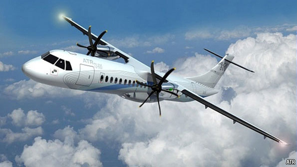
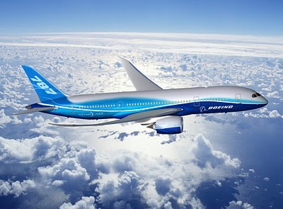
Virtually all jet powered aircraft have an air brake or, in the case of most airliners, lift spoilers that also act as air brakes. Propeller driven aircraft benefit from the natural braking effect of the propeller when the engine is throttled back, but jet powered aircraft have no such innate braking effect and must utilise air brakes to control descent speed.

Saturday, April 9, 2016

The "Rudder'

On an aircraft, the rudder is a directional control surface along with the rudder-like elevator (usually attached to horizontal tail structure, if not a slab elevator ) and ailerons (attached to the wings) that control pitch and roll, respectively. The rudder is usually attached to the fin (or vertical stabilizer) which allows the pilot to control yaw about the vertical axis, i.e. change the horizontal direction in which the nose is pointing. The rudder's direction in aircraft since the "Golden Age" of flight between the two World Wars into the 21st century has been manipulated with the movement of a pair of counter-moving foot pedals by the pilot, while during the pre-1919 era rudder control was most often operated with by a center-pivoted, solid "rudder bar" which usually had pedal and/or stirrup-like hardware on its ends to allow the pilot's feet to stay close to the ends of the bar's rear surface.
In practice, both aileron and rudder control input are used together to turn an aircraft, the ailerons imparting roll, the rudder imparting yaw, and also compensating for a phenomenon called adverse yaw. A rudder alone will turn a conventional fixed-wing aircraft, but much more slowly than if ailerons are also used in conjunction. Use of rudder and ailerons together produces co-ordinated turns, in which the longitudinal axis of the aircraft is in line with the arc of the turn, neither slipping (under-ruddered), nor skidding (over-ruddered). Improperly ruddered turns at low speed can precipitate a spin which can be dangerous at low altitudes.
Sometimes pilots may intentionally operate the rudder and ailerons in opposite directions in a maneuver called a slip. This may be done to overcome crosswinds and keep the fuselage in line with the runway, or to more rapidly lose altitude by increasing drag, or both. The pilots of Air Canada Flight 143 used a similar technique to land the plane as it was too high above the glideslope.
Any aircraft rudder is subject to considerable forces that determine its position via a force or torque balance equation. In extreme cases these forces can lead to loss of rudder control or even destruction of the rudder, as on American Airlines Flight 587 (the same principles also apply to water vessels, of course, but it is more important for aircraft because they have lower engineering margins). Maximum rudder deflection is controlled by rudder travel limiter. The largest achievable angle of a rudder in flight is called its blowdown limit; it is achieved when the force from the air or blowdown equals the maximum available hydraulic pressure.
In multi-engined aircraft where the engines are off the centre line, the rudder may be used to trim against the yaw effect of asymmetric thrust, for example in the event of engine failure. Further, on large jet airliners, during non-autopilot flight, the rudder is mainly used to compensate for side wind components. Turns can be done by the use of ailerons only.
For taxiing and during the beginning of the take-off, aircraft are steered by a combination of rudder input as well as turning the nosewheel or tailwheel. At slow speeds the nosewheel or tailwheel has the most control authority, but as the speed increases the aerodynamic effects of the rudder increases, thereby making the rudder more and more important for yaw control. In some aircraft (mainly small aircraft) both of these mechanisms are controlled by the rudder pedals so there is no difference to the pilot. In other aircraft there is a special tiller controlling the wheel steering and the pedals control the rudder. For these aircraft there is usually a speed stipulated at which the pilots should change from steering with the wheels to steering with the rudder. This speed is usually in the neighbourhood of 80 knots.

The "Turboprop jet engine"

A turboprop engine is a turbine engine that drives an aircraft propeler.In contrast to a turbojet, the engine's exhaust gases do not contain enough energy to create significant thrust, since almost all of the engine's power is used to drive the propeller.
The propeller is coupled to the turbine through a reduction gear that converts the high RPM, low torque output to low RPM, high torque. The propeller itself is normally a constant speed (variable pitch) type similar to that used with larger reciprocating aircraft engines.
Turboprop engines are generally used on small subsonic aircraft, but some aircraft outfitted with turboprops have cruising speeds in excess of 500 kt (926 km/h, 575 mph).Large military and civil aircraft, such as the Lockheed L-188 Electra and the Tupolev Tu-95, have also used turboprop power. The Airbus A400M is powered by four Europrop TP400 engines, which are the third most powerful turboprop engines ever produced, after the Kuznetsov NK-12 and Progress D-27.
In its simplest form a turboprop consists of an intake, compressor, combustor, turbine, and a propelling nozzle. Air is drawn into the intake and compressed by the compressor. Fuel is then added to the compressed air in the combustor, where the fuel-air mixture then combusts. The hot combustion gases expand through the turbine. Some of the power generated by the turbine is used to drive the compressor. The rest is transmitted through the reduction gearing to the propeller. Further expansion of the gases occurs in the propelling nozzle, where the gases exhaust to atmospheric pressure. The propelling nozzle provides a relatively small proportion of the thrust generated by a turboprop.
Turboprops are most efficient at flight speeds below 725 km/h (450 mph; 390 knots) because the jet velocity of the propeller (and exhaust) is relatively low. Due to the high price of turboprop engines, they are mostly used where high-performance short-takeoff and landing (STOL) capability and efficiency at modest flight speeds are required. The most common application of turboprop engines in civilian aviation is in small commuter aircraft, where their greater power and reliability over reciprocating engines offsets their higher initial cost and fuel consumption. Turboprop airliners now operate at near the same speed as small turbofan-powered aircraft but burn two-thirds of the fuel per passenger. However, compared to a turbojet (which can fly at high altitude for enhanced speed and fuel efficiency) a propeller aircraft has a much lower ceiling. Turboprop-powered aircraft have become popular for bush airplanes such as the Cessna Caravan and Quest Kodiak as jet fuel is easier to obtain in remote areas than is aviation-grade gasoline (avgas).

Wednesday, December 23, 2015

The airplane's flaps

  Flaps are devices used to alter the lift characteristics of a wing and are mounted on the trailing edges of the wings of a fixed-wing aircraft to reduce the speed at which the aircraft can be safely flown and to increase the angle of descent for landing. They do this by lowering the stall speed and increasing the drag. Flaps shorten takeoff and landing distances.
Extending flaps increases the camber or curvature of the wing, raising the maximum lift coefficient — the lift a wing can generate. This allows the aircraft to generate as much lift, but at a lower speed, reducing the stalling speed of the aircraft, or the minimum speed at which the aircraft will maintain flight. Extending flaps increases drag, which can be beneficial during approach and landing, because it slows the aircraft. On some aircraft, a useful side effect of flap deployment is a decrease in aircraft pitch angle which lowers the nose thereby improving the pilot's view of the runway over the nose of the aircraft during landing. However the flaps may also cause pitch-up depending on the type of flap and the location of the wing.
There are many different types of flaps used, with the specific choice depending on the size, speed and complexity of the aircraft on which they are to be used, as well as the era in which the aircraft was designed. Plain flaps, slotted flaps, and Fowler flaps are the most common. Krueger flaps are positioned on the leading edge of the wings and are used on many jet airliners.
The Fowler, Fairey-Youngman and Gouge types of flap increase the wing area in addition to changing the camber. The larger lifting surface reduces wing loading and allows the aircraft to generate the required lift at a lower speed and reduces stalling speed.


 The flap types
  • Plain flap: the rear portion of airfoil rotates downwards on a simple hinge mounted at the front of the flap. The Royal Aircraft Factory and National Physical Laboratory in the United Kingdom tested flaps in 1913 and 1914, but these were never installed in an actual aircraft.In 1916, the Fairey Aviation Company made a number of improvements to a Sopwith Baby they were rebuilding, including their Patent Camber Changing Gear, making the Fairey Hamble Baby as they renamed it, the first aircraft to fly with flaps. These were full span plain flaps which incorporated ailerons, making it also the first instance of flaperons.[5] Fairey were not alone however, as Breguet soon incorporated automatic flaps into the lower wing of their Breguet 14 reconnaissance/bomber in 1917.Due to the greater efficiency of other flap types, the plain flap is normally only used where simplicity is required.
Flaps and high lift devices. Gurney flap exaggerated for clarity. Blown flap skipped as it is modified from any other type. Pale lines indicate line of movement, and green indicates flap setting used during dive.
  • Split flap: the rear portion of the lower surface of the airfoil hinges downwards from the leading edge of the flap, while the upper surface stays immobile. Like the plain flap, this can cause large changes in longitudinal trim, pitching the nose either down or up, and tends to produce more drag than lift. At full deflection, a split flaps acts much like a spoiler, producing lots of drag and little or no lift. It was invented by Orville Wright and James M. H. Jacobs in 1920, but only became common in the 1930s and was then quickly superseded. The Douglas DC-3 & C-47 used a split flap.
  • Slotted flap: a gap between the flap and the wing forces high pressure air from below the wing over the flap helping the airflow remain attached to the flap, increasing lift compared to a split flap.Additionally, lift across the entire chord of the primary airfoil is greatly increased as the velocity of air leaving its trailing edge is raised, from the typical non-flap 80% of freestream, to that of the higher-speed, lower-pressure air flowing around the leading edge of the slotted flap. Any flap that allows air to pass between the wing and the flap is considered a slotted flap. The slotted flap was a result of research at Handley-Page, a variant of the slot that dates from the 1920s, but wasn't widely used until much later. Some flaps use multiple slots to further boost the effect.
  • Fowler flap: split flap that slides backward flat, before hinging downward, thereby increasing first chord, then camber. The flap may form part of the upper surface of the wing, like a plain flap, or it may not, like a split flap, but it must slide rearward before lowering. It may provide some slot effect, but this is not a defining feature of the type. Invented by Harlan D. Fowler in 1924, and tested by Fred Weick at NACA in 1932. They were first used on the Martin 146 prototype in 1935, and in production on the 1937 Lockheed Electra, and are still in widespread use on modern aircraft, often with multiple slots.

  • Junkers flap: a slotted plain flap where the flap is fixed below the trailing edge of the wing, rotating about its forward edge, and usually forming the "inboard" hinged section (closer to the root) of the Junkers Doppelflügel, or "double-wing" style of wing trailing edge control surfaces (including the outboard-mounted ailerons), which hung just below and behind the wing's fixed trailing edge. When not in use, it has more drag than other types, but is more effective at creating additional lift than a plain or split flap, while retaining their mechanical simplicity. Invented by Otto Mader at Junkers in the late 1920s, they were historically most often seen on both the Ju 52/3m airliner/cargo plane, and the Ju 87 Stuka dive bomber, though the same wing control surface can be also be found on many modern ultralights.
  • Gouge flap: a type of split flap that slides backward along curved tracks that force the trailing edge downward, increasing chord and camber without affecting trim or requiring any additional mechanisms. It was invented by Arthur Gouge for Short Brothers in 1936 and used on the Short Empire and Sunderland flying boats, which used the very thick Shorts A.D.5 airfoil. Short Brothers may have been the only company to use this type.

  • Fairey-Youngman flap: drops down (becoming a Junkers Flap) before sliding aft and then rotating up or down. Fairey was one of the few exponents of this design, which was used on the Fairey Firefly and Fairey Barracuda. When in the extended position, it could be angled up (to a negative angle of incidence) so that the aircraft could be dived vertically without needing excessive trim changes.
  • Zap Flap or commonly, but incorrectly, Zapp Flap: Invented by Edward F. Zaparka while he was with Berliner/Joyce and tested on a General Aircraft Corporation Aristocrat in 1932 and on other types periodically thereafter, but it saw little use on production aircraft other than on the Northrop P-61 Black Widow. The leading edge of the flap is mounted on a track, while a point at mid chord on the flap is connected via an arm to a pivot just above the track. When the flap's leading edge moves aft along the track, the triangle formed by the track, the shaft and the surface of the flap (fixed at the pivot) gets narrower and deeper, forcing the flap down.
  • Krueger flap: hinged flap, which folds out from under the wing's leading edge while not forming a part of the leading edge of the wing when retracted. This increases the camber and thickness of the wing, which in turn increases lift and drag. This is not the same as a leading edge droop flap, as that is formed from the entire leading edge. Invented by Werner Krüger in 1943 and evaluated in Goettingen, Krueger flaps are found on many modern swept wing airliners.
  • Gurney flap: A small fixed perpendicular tab of between 1 and 2% of the wing chord, mounted on the high pressure side of the trailing edge of an airfoil. It was named for racing car driver Dan Gurney who rediscovered it in 1971, and has since been used on some helicopters such as the Sikorsky S-76B to correct control problems without having to resort to a major redesign. It boosts the efficiency of even basic theoretical airfoils (made up of a triangle and a circle overlapped) to the equivalent of a conventional airfoil. The principle was discovered in the 1930s, but was rarely used and was then forgotten. Late marks of the Supermarine Spitfire used a bead on the trailing edge of the elevators, which functioned in a similar manner.
  • Leading edge droop: entire leading edge of the wing rotating downward,effectively increasing camber, but slightly reducing chord. Most commonly found on fighters with very thin wings unsuited to other leading edge high lift devices.
  • Blown flaps: also known as Boundary Layer Control Systems, are systems that blow engine air over the upper surface of any of the previously mentioned types of flap to improve lift characteristics. Two types exist - the original type blew air out of channels or holes in the surface of the flap, while newer systems simply blow engine exhaust over the top of the flap. These require ample reserves of power and are maintenance intensive thus limiting their use, but they significantly reduce the stalling speed. Although invented by the British, the first production aircraft with blown flaps was the Lockheed F-104 Starfighter. The later type was trialled on the Boeing YC-14 in 1976.
  • Flexible flap or FlexFoil: modern interpretation of wing warping, internal mechanical actuators bend a lattice that changes the airfoil shape. It may have a flexible gap seal at the transition between fixed and flexible airfoils.
  • Controls that look like flaps, but are not:
    • Handley Page leading edge slats/slots may be confused for flaps, but are mounted on the top of the wings' leading edge and while they may be either fixed or retractable, when deployed they provide a slot or gap under the slat to force air against the top of the wing, which is absent on a Krueger flap. They offer excellent lift and enhance controllability at low speeds. Other types of flaps may be equipped with one or more slots to increase their effectiveness, a typical setup on many modern airliners. These are known as slotted flaps as described above. Frederick Handley Page experimented with fore and aft slot designs in the 20s and 30s.
    • Spoilers may also be confused for flaps, but are intended to create drag and reduce lift by "spoiling" the airflow over the wing. A spoiler is much larger than a Gurney flap, and can be retracted. Spoilers are usually installed mid chord on the upper surface of the wing, but may also be installed on the lower surface of the wing as well.
    • Air brakes are used on high performance combat aircraft to increase drag, allowing the aircraft to decelerate rapidly. They may be installed either on the wings or fuselage and differ from flaps and spoilers in that they are not intended to reduce lift and are built strongly enough to be deployed at much higher speeds.
    • Ailerons are similar to flaps (and work the same way), but are intended to provide lateral control, rather than to change the lifting characteristics of both wings together, and so operate differentially - when an aileron on one wing increases the lift, the opposite aileron does not, and will often work to decrease lift. Some aircraft use flaperons, which combine both the functionality of flaps and ailerons in a single control, working together to increase lift, but to slightly different degrees so the aircraft will roll toward the side generating the least lift. Flaperons were used by the Fairey Aviation Company as early as 1916, but didn't become common until after World War II.

Thursday, November 5, 2015

The "Turbofan jet engine"


The turbofan or fanjet is a type of airbreathing jet engine that is widely used in aircraft propulsion. The word "turbofan" is a portmanteau of "turbine" and "fan": the turbo portion refers to a gas turbine engine which takes mechanical energy from combustion,and the fan, a ducted fan that uses the mechanical energy from the gas turbine to accelerate air rearwards. Thus, whereas all the air taken in by a turbojet passes through the turbine (through the combustion chamber), in a turbofan some of that air bypasses the turbine. A turbofan thus can be thought of as a turbojet being used to drive a ducted fan, with both of those contributing to the thrust. The ratio of the mass-flow of air bypassing the engine core compared to the mass-flow of air passing through the core is referred to as the bypass ratio. The engine produces thrust through a combination of these two portions working in concert; engines that use more jet thrust relative to fan thrust are known as low bypass turbofans, conversely those that have considerably more fan thrust than jet thrust are known as high bypass. Most commercial aviation jet engines in use today are of the high-bypass type, and most modern military fighter engines are low-bypass. Afterburners are not used on high-bypass turbofan engines but may be used on either low-bypass turbofan or turbojet engines.
Most of the air flow through a high-bypass turbofan is low-velocity bypass flow: even when combined with the much higher velocity engine exhaust, the average exhaust velocity is considerably lower than in a pure turbojet. Turbojet engine noise is predominately jet noise from the high exhaust velocity, therefore turbofan engines are significantly quieter than a pure-jet of the same thrust with jet noise no longer the predominant source. Other noise sources are the fan, compressor and turbine. Jet noise is reduced with chevrons, sawtooth patterns on the exhaust nozzles, on the Rolls-Royce Trent 1000 and General Electric GEnx engines used on the Boeing 787.
Since the efficiency of propulsion is a function of the relative airspeed of the exhaust to the surrounding air, propellers are most efficient for low speed, pure jets for high speeds, and ducted fans in the middle. Turbofans are thus the most efficient engines in the range of speeds from about 500 to 1,000 km/h (310 to 620 mph), the speed at which most commercial aircraft operate. Turbofans retain an efficiency edge over pure jets at low supersonic speeds up to roughly Mach 1.6, but have also been found to be efficient when used with continuous afterburner at Mach 3 and above.
The vast majority of turbofans follow the same basic design, with a large fan at the front of the engine and a relatively small jet engine behind it. There have been a number of variations on this design, however, including rear-mounted fans which can easily be added to an existing pure-jet design, or designs that combine a low-pressure turbine and a fan stage in a single rear-mounted unit.

Monday, October 26, 2015

The airplane


An airplane or aeroplane (informally plane) is a powered, fixed-wing aircraft that is propelled forward by thrust from a jet engine or propeller. Airplanes come in a variety of sizes, shapes, and wing configurations. The broad spectrum of uses for airplanes includes recreation, transportation of goods and people, military, and research. Commercial aviation is a massive industry involving the flying of tens of thousands of passengers daily on airliners. Most airplanes are flown by a pilot on board the aircraft, but some are designed to be remotely or computer-controlled.
The Wright brothers invented and flew the first airplane in 1903, recognized as "the first sustained and controlled heavier-than-air powered flight". They built on the works of George Cayley dating from 1799, when he set forth the concept of the modern airplane (and later built and flew models and successful passenger-carrying gliders). Between 1867 and 1896, the German pioneer of human aviation Otto Lilienthal also studied heavier-than-air flight. Following its limited use in World War I, aircraft technology continued to develop. Airplanes had a presence in all the major battles of World War II. The first jet aircraft was the German Heinkel He 178 in 1939. The first jet airliner, the de Havilland Comet, was introduced in 1952. The Boeing 707, the first widely successful commercial jet, was in commercial service for more than 50 years, from 1958 to at least 2013.